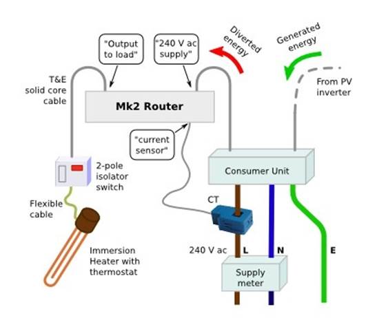
PV routeur pour les nuls
Ce document decrit comment realiser un PV routeur de la facon la plus simple possible. (source : https://learn.openenergymonitor.org/ et http://mk2pvrouter.co.uk/
Merci a Robin Emley qui a mis au point ce systeme genial.
J'ai fait ce tuto avec le souci de limiter au strict minimum le nombre de composant a souder.
Aucun composant sous 230V n'est introduit sur la carte pour rester accessible au plus grand nombre.
Liste de course :
- 1 arduino uno : UNO_R3
-

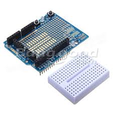
- 1 arduino proto shield pcb
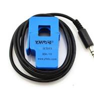
- Une pince ampermetrique sortie tension SCT-013-030SCT-013-030
-
-
- 1 alimentation a decoupage 7.5V DC 1A alim
-

- 1 transfo a bobine 9V AC/AC en ligne ou en magasin
-

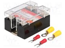
- 1 relais statique (sans detection de zero) QLT POWER SSR-2528RD3 SSR
-
- un radiateur adaptable sur rail DIN pour le relais radia
-

- Boitier plastique 115x90x55 boitier
-

- Prises BNC chassis bnc
-

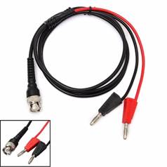
- Cordon BNC cable_BNC
-
- Prise jack stereo 3.5mm chassis jack
-

- Prise 5.5x2.1mm chassis prise_5.5
-

- cables Dupont : dupont lines
-

Voila j'ai pas fait le calcul exact mais on doit etre a moins de50\80 surtout si on recupere un vieux transfo a bobine au lieu de l'acheter. Ne pas oublier de le modifier si celui-ci sort du courant continu (DC) au lieu du courant alternatif (AC)
Maintenant voici le montage electronique a realiser sur le pcb proto special arduino :
Mesure de tension

Calcul de R2
Il faut MESURER la tension de sortie de votre transfo AC avec un multimetre en position tension alternative.
R2 = 0.7xV -1
Par exemple si on lit 10V alors
R2 = 0.7*10 -1 = 6 kOhm (prendre la valeur superieure la plus proche)
La sortie de ce montage (arduino input sur le schema) est a relie a l'entree A1 de l'arduino .
En photos :

La resistance R2 est donc celle sur la gauche. Toutes les autres sont des resistances de 1kOhm donc pas de risque de se tromper ;-)
Mesure de courant
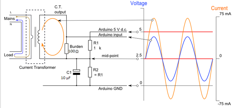
Ben c'est un peu pareil sauf qu'il y 2 resistances en moins si vous avez achete une pince ampermetrique a sortie tension (comme indique plus haut). Sinon si vous avez commande/recu (comme moi) une sonde a sortie courant alors il faut mettre la resistance de 100 Ohm pour un abonnement de 30A ou 56 Ohm pour un abonnement de 45A
Si vous avez une pince avec sortie tension alors il ne faut rien mettre a la place de la resistance de 100 Ohm.
La sortie de ce montage (arduino input sur le schema) est a relie a l'entree A0 de l'arduino .
En photos :
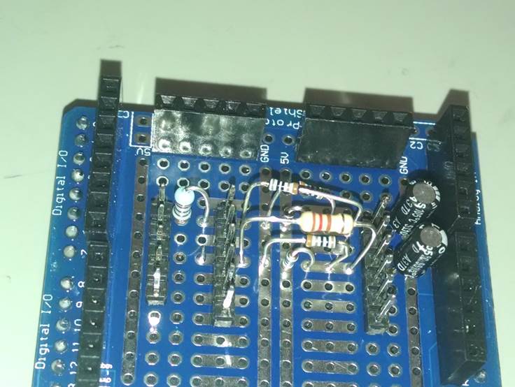
On remarque la resistance (burden) de 120 Ohm (j'avais plus de 100 ohm !) au-dessus des resistances de 1Kohm.
On peut aussi voir que j'ai implante 3 series de picots qui permettrons de faire les liaisons entree/sortie des signaux gr\E2ce aux c\E2bles Dupont.
En dessous :

Ne pas oublier de faire les petits pontages a gauche et a droite sur la photo pour respecter les schemas electriques ci-dessus\85
Faire les connections avec les c\E2bles Dupont entre la sortie de chaque voie de mesure et les entrees de l'arduino :

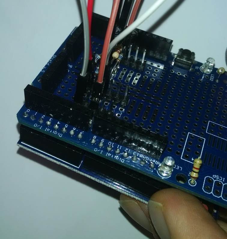
Voici une image qui montre les Entrees/sorties de l'arduino en detail.
Ces E/S sont deja reliees au \AB proto shield \BB que l'on vient de fabriquer.
Il suffit donc de mettre
- Un c\E2ble (rouge sur la photo ci-dessus) entre la sortie de notre montage de mesure de tension et l'entree A1 de l'arduino.
- Un c\E2ble (blanc sur la photo ci-dessus) entre la sortie de notre montage de mesure de courant et l'entree A0 de l'arduino.

Et voila la partie purement electronique est finie !!!
Tout le reste n'est que de la mecanique et de la connectique.
En photos :
Connectique des signaux d'entrees (tension et courant) :

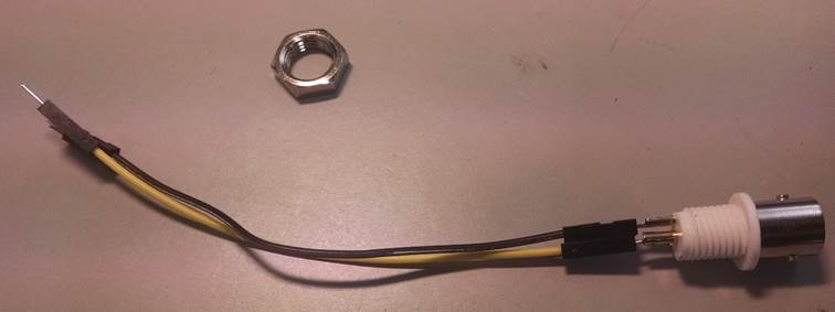
Le plus simple est de prendre des c\E2bles Dupont male-femelle et de souder la partie male sur les connecteurs ch\E2ssis.
Pour le connecteur de sortie (vers le relais) on utilise des c\E2bles Dupont male-male.
Maintenant c'est l'heure du sandwich (miam-miam)
Pour faire un joli sandwich il suffit d'embrocher le shield que l'on vient de creer sur l'arduino
Attention a bien aligner toutes les papates\85
Le boitier :
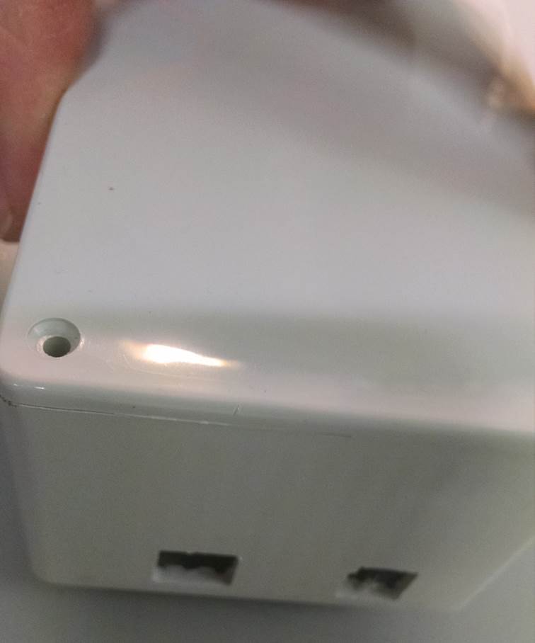
On fait des trous carres d'un cote \85
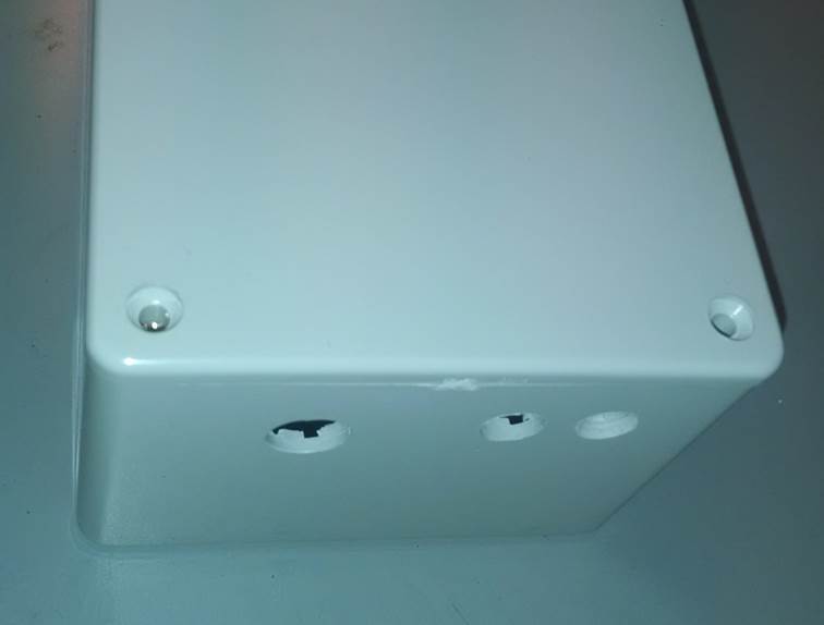
Puis des ronds de l'autre cote :
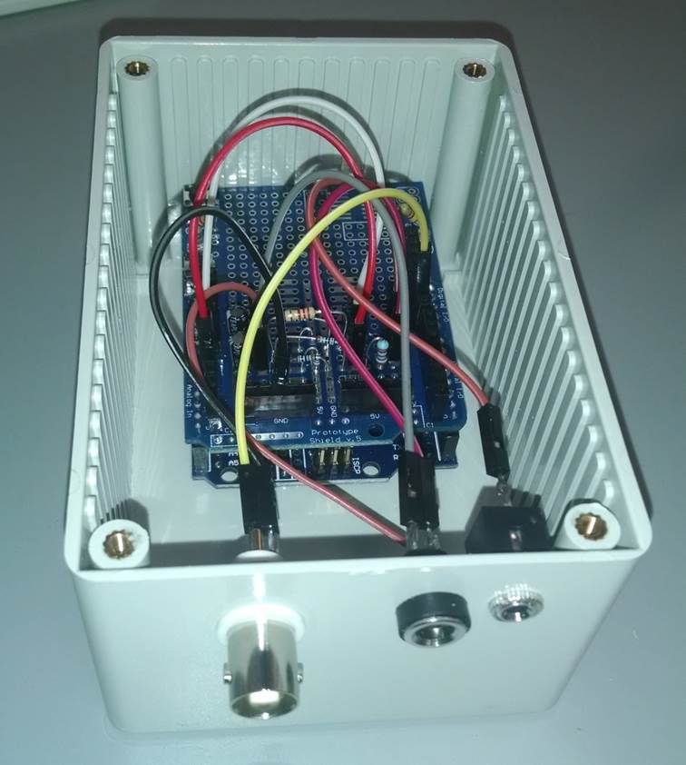
On assemble tout ca :

- On remarque le c\E2ble jaune entre la sortie 9 de l'arduino et le connecteur BNC qui ira au relais statique. Il faut aussi relier sa masse. Cable noir qui va des connecteurs (en haut a droite) marques GND a la masse de la BNC.
Fini !!! y'a plus qu'a tester \85
Test du PV routeur
Banc de test :
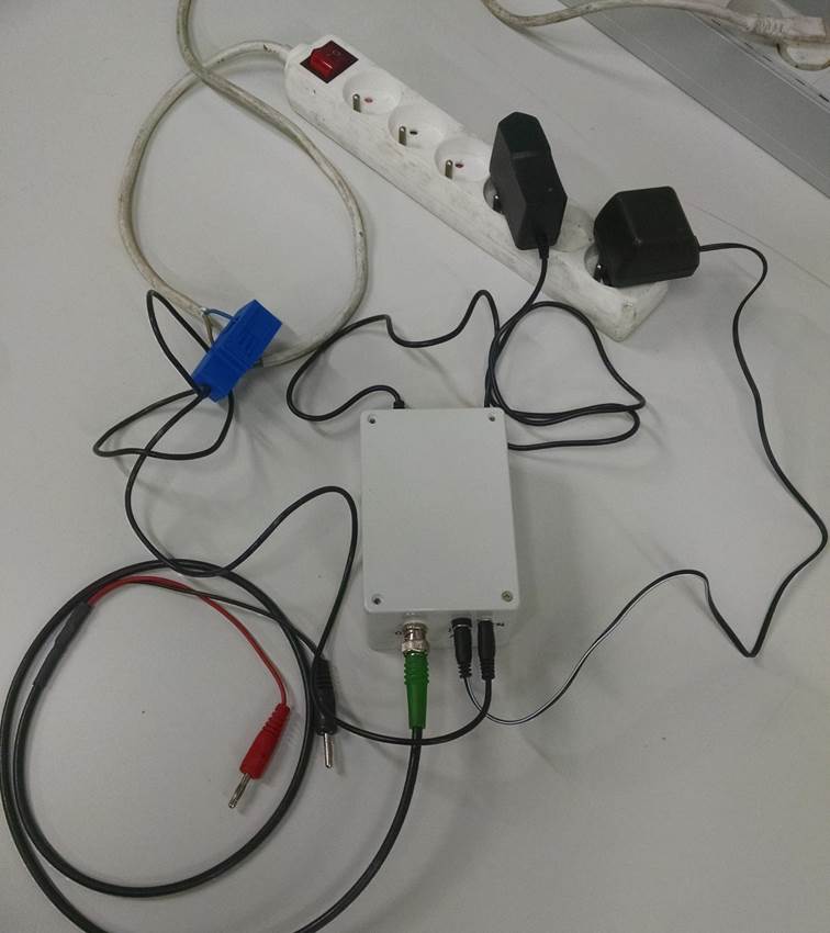

Il faut bien separer les fils pour ne mesurer qu'un conducteur a la fois.
On connecte l'arduino au PC avec un cab e USB type AB (celui pour l'imprimante).
On installe l'IDE (l'environnement de developpement) sur le PC
Version 1.8.4 a telecharger ici : https://www.arduino.cc/en/Main/OldSoftwareReleases
On installe les drivers pour l'arduino UNO : http://283.mytrademe.info/ch340.html
Menu outils-> type de carte-> UNO
Menu outils-> PORT-> ComX ou X represente le port sur lequel est installe votre arduino.
On efface ce qu'il y a dans la fenetre d'edition
On y colle le code ci-dessous :
//
minMaxAndRangeChecker
// A
simple tool to investigate the ADC values that are seen at the
//
first four analogue inputs of an Atmega chip, as used on an emonTx
//
//
Robin Emley (calypso_rae on the Open Energy Monitor forum)
//
//
20th April 2013
//
int
val_a0, val_a1, val_a2, val_a3;
int
minVal_a0, minVal_a1, minVal_a2, minVal_a3;
int
maxVal_a0, maxVal_a1, maxVal_a2, maxVal_a3;
int
loopCount = 0;
unsigned
long timeAtLastDisplay = 0;
byte
displayLineCounter = 0;
void
setup(void)
{
Serial.begin(9600);
Serial.print("ready ...");
delay(7000);
Serial.println ();
Serial.println(" The Min, Max and Range
ADC values for analog inputs 0 to 3:");
}
void
loop(void)
{
val_a0 = analogRead(0); // CT2
val_a1 = analogRead(1); // CT3
val_a2 = analogRead(2); // Vsensor
val_a3 = analogRead(3); // CT1
if (val_a0 < minVal_a0) { minVal_a0 =
val_a0;}
if (val_a0 > maxVal_a0) { maxVal_a0 =
val_a0;}
if (val_a1 < minVal_a1) { minVal_a1 =
val_a1;}
if (val_a1 > maxVal_a1) { maxVal_a1 =
val_a1;}
if (val_a2 < minVal_a2) { minVal_a2 =
val_a2;}
if (val_a2 > maxVal_a2) { maxVal_a2 =
val_a2;}
if (val_a3 < minVal_a3) { minVal_a3 =
val_a3;}
if (val_a3 > maxVal_a3) { maxVal_a3 =
val_a3;}
unsigned long timeNow = millis();
if ((timeNow - timeAtLastDisplay) >= 3000)
{
timeAtLastDisplay = timeNow;
displayVal(minVal_a0);
displayVal(maxVal_a0);
displayVal(maxVal_a0 - minVal_a0);
Serial.print("; ");
displayVal(minVal_a1);
displayVal(maxVal_a1);
displayVal(maxVal_a1 - minVal_a1);
Serial.print("; ");
displayVal(minVal_a2);
displayVal(maxVal_a2);
displayVal(maxVal_a2 - minVal_a2);
Serial.print("; ");
displayVal(minVal_a3);
displayVal(maxVal_a3);
displayVal(maxVal_a3 - minVal_a3);
Serial.println();
resetMinAndMaxValues();
displayLineCounter++;
if (displayLineCounter >= 5)
{
Serial.println();
displayLineCounter = 0;
delay(2000); // to allow time for data to
be accessed
}
}
}
void
resetMinAndMaxValues()
{
minVal_a0 = 1023, minVal_a1 = 1023, minVal_a2
= 1023, minVal_a3 = 1023;
maxVal_a0 = 0, maxVal_a1 = 0, maxVal_a2 = 0,
maxVal_a3 = 0;
}
void displayVal(int
intVal)
{
char strVal[4];
byte lenOfStrVal;
// display the value as a right-justified
integer
// intVal = surplusPowerSetting; // apply
integer rounding
itoa(intVal, strVal, 10); // decimal
conversion to string
lenOfStrVal = strlen(strVal); // determine
length of string
for (int i = 0; i < (4 - lenOfStrVal);
i++)
{
Serial.print(' ');
}
Serial.print(strVal);
}
On enregistre tout ca sur le PC sous le nom
minMaxAndRangeChecker.ino
par exemple
Puis : Menu croquis -> televerser.
On ouvre le moniteur serie : Menu outils -> moniteur serie
Une autre fenetre s'ouvre. Regler le debit (baud rate a 9600 si ce n'est pas le reglage par defaut)
Dans un premier temps on ne bascule pas l'inter 230V de la multiprise. L'arduino est uniquement alimente (en 5V) par le port USB du PC et les valeurs de l'entree tension et l'entree courant sont donc egale a 0.
On voit apparaitre des valeurs dans le moniteur serie :
Entree A0
Premiere colonne = min en bits (de 0 a 1023)
Deuxieme colonne = max (de 0 a 1023)
Troisieme colonne = ecart (max-min)
Entree A1
Premiere colonne = min en bits (de 0 a 1023)
Deuxieme colonne = max (de 0 a 1023)
Troisieme colonne = ecart (max-min)
Entree A2
Etc etc
On doit lire des valeurs proches de 512 pour A0 at A1.
510 514 4 508 511 3
Sinon c'est qu'il y a un probleme sur le
pont diviseur de tension de la voie concernee (c'est les 2 resistances 1Kohm)
Ensuite on ferme l'inter 230V de la multiprise.
Sur A0 on lit toujours a peu pres
510 514 4
Sur A1 on doit lire environ
110 912 802
Min max ecart
On branche un seche cheveux ou une bouilloire electrique sur la multiprise.
Lorsque l'on met ce consommateur en route l'ecart sur A0 doit devenir plus grand
Par ex pour une bouilloire de 2300W (cad 10A) on lit a peu pres :
415 606 191
C'est tout bon ? parfait.
On coupe la bouilloire, on eteint la multiprise gr\E2ce a son interrupteur.
Maintenant on va flasher le code final (merci Robin) dans l'arduino :
On ferme la fenetre du moniteur serie
On efface tout ce qu'il y a dans la fenetre de l'IDE.
On copie-colle le code ci-dessous.
//Mk2_PV_phaseAngle_APPER.ino
//
This is a cut-down version of my stand-alone sketch for diverting suplus
// PV
power to a dump load using a triac. The
original version, which includes
//
more explanation and 'debug' code to support off-line working, may be found at
//
http://openenergymonitor.org/emon/node/841
//
//
Further modified to use phase-angle control of the triac rather than
//
burst mode
//
// Robin Emley (calypso_rae on
Open Energy Monitor Forum)
// October 2012
// Further modified by lebritish
to add software wathchdtog
// September 2017
/*
Circuit
for monitoring pulses from a supply meter using checkLedStatus():
----------------> +5V
|
/
\ 8K2
/
|
---------------------> dig 2
| |
-->
/ |
-->
\ _
LDR
/ - 0.01uF
| |
----------------------> GND
*/
#include
<avr/wdt.h>
#define
POSITIVE 1
#define
NEGATIVE 0
#define
ON 1 // for use with trigger device
(active was low now high)
#define
OFF 0
//#define
ON 1 // for use with LED( active high)
//#define
OFF 0
byte
outputPinForLed = 13;
byte
outputPinForTrigger = 10;
byte
outputPinForPAcontrol = 9;
byte
voltageSensorPin = 1;
byte
currentSensorPin = 0;
byte
ledDetectorPin = 2; // digital
byte
ledRepeaterPin = 10; // digital
float
safetyMargin_watts = 10; //
<<<------ increase for more export
long
cycleCount = 0;
int
samplesDuringThisMainsCycle = 0;
byte
nextStateOfTriac;
float
cyclesPerSecond = 50; // use float to ensure accurate maths
long
noOfSamplePairs = 0;
byte
polarityNow;
boolean
triggerNeedsToBeArmed = false;
boolean
beyondStartUpPhase = false;
float
energyInBucket = 0; // mimics the operation of a meter at the grid connection
point.
//float
energyInBucket_4trial = 0; // as entered by used for p-a control trials
int
capacityOfEnergyBucket = 3600; // 0.001 kWh = 3600 Joules
int
sampleV,sampleI; // voltage &
current samples are integers in the ADC's input range 0 - 1023
int
lastSampleV; // stored value from the
previous loop (HP filter is for voltage samples only)
float
lastFilteredV,filteredV; // voltage values after HP-filtering to remove
the DC offset
float
prevDCoffset; // <<--- for
LPF
float
DCoffset; // <<--- for
LPF
float
cumVdeltasThisCycle; // <<--- for
LPF
float
sampleVminusDC; // <<---
for LPF
float
sampleIminusDC; // <<---
used with LPF
float
lastSampleVminusDC; // <<---
used with LPF
float
sumP; // cumulative sum of power calculations within
each mains cycle
float
PHASECAL;
float
POWERCAL; // To convert the product of
raw V & I samples into Joules.
float
VOLTAGECAL; // To convert raw voltage samples into volts. Used for determining when
// the trigger device can be
safely armed
//
items for LED monitoring
byte
ledState, prevLedState;
boolean
ledRecentlyOnFlag = false;
unsigned
long ledOnAt;
float
energyInBucket_4led = 0;
float
energyLevelAtLastLedPulse;
//
items for phase-angle control of triac
boolean
firstLoopOfHalfCycle;
boolean
phaseAngleTriggerActivated;
unsigned
long timeAtStartOfHalfCycleInMicros;
unsigned
long firingDelayInMicros;
void
setup()
{
// immediately disable watchdog timer so set
will not get interrupted
wdt_disable();
// the following forces a pause before
enabling WDT. This gives the IDE a chance to
// call the bootloader in case something
dumb happens during development and the WDT
// resets the MCU too quickly. Once the
code is solid, remove this.
// delay(2L * 1000L);
// enable the watchdog timer. There are a
finite number of timeouts allowed (see wdt.h).
// Notes I have seen say it is unwise to go
below 250ms as you may get the WDT stuck in a
// loop rebooting.
// The timeouts I'm most likely to use are:
// WDTO_1S
// WDTO_2S
// WDTO_4S
// WDTO_8S
wdt_enable(WDTO_8S);
Serial.begin(9600);
Serial.setTimeout(20); // for rapid input of
data (default is 1000ms)
pinMode(outputPinForTrigger, OUTPUT);
pinMode(outputPinForPAcontrol, OUTPUT);
pinMode(outputPinForLed, OUTPUT);
POWERCAL = 0.042; // Units are Joules per
ADC-level squared. Used for converting
the product of
// voltage and current
samples into Joules.
// To determine this value, note the rate that
the energy bucket's
// level increases when a known
load is being measured at a convenient
// test location (e.g using a mains extention with the outer cover
removed so that
// the current-clamp can
fit around just one core. Adjust
POWERCAL so that
// 'measured value' =
'expected value' for various loads. The
value of
// POWERCAL is not critical
as any absolute error will cancel out when
// import and export flows
are balanced.
VOLTAGECAL = (float)679 / 471; // Units are
Volts per ADC-level.
// This value is used
to determine when the voltage level is suitable for
// arming the external
trigger device. To set this value, note
the min and max
// numbers that are
seen when measuring 240Vac via the voltage sensor, which
// is 678.8V
p-t-p. The range on my setup is 471
meaning that I'm under-reading
// voltage by
471/679. VOLTAGECAL therefore need to be
the inverse of this, i.e.
// 679/471 or 1.44
PHASECAL = 1.0; // the default or 'do nothing' value
}
void
loop() // each loop is for one pair of V & I measurements
{
// reset the watchdog timer every loop
wdt_reset();
noOfSamplePairs++; // for stats only
samplesDuringThisMainsCycle++; // for power calculation at the start of each
mains cycle
// store values from previous loop
lastSampleV=sampleV; // for digital high-pass filter
lastFilteredV = filteredV; // for HPF, used to identify the start of
each mains cycle
lastSampleVminusDC = sampleVminusDC; // for phasecal calculation
// Get
the next pair of raw samples. Because
the CT generally adds more phase-advance
//
than the voltage sensor, it makes sense to sample current before voltage
sampleI = analogRead(currentSensorPin);
sampleV = analogRead(voltageSensorPin);
// remove the DC offset from these samples as
determined by a low-pass filter
sampleVminusDC = sampleV - DCoffset;
sampleIminusDC = sampleI - DCoffset;
// a high-pass filter is used just for
determining the start of each mains cycle
filteredV =
0.996*(lastFilteredV+sampleV-lastSampleV);
// Establish the polarities of the latest and
previous filtered voltage samples
byte polarityOfLastReading = polarityNow;
if(filteredV >= 0)
polarityNow = POSITIVE;
else
polarityNow = NEGATIVE;
if (polarityNow == POSITIVE)
{
if (polarityOfLastReading != POSITIVE)
{
// This is the start of a new mains cycle
(just after the +ve going z-c point)
cycleCount++; // for stats only
firstLoopOfHalfCycle = true;
// checkLedStatus(); // a really useful
function, but can be commented out if not required
// update the Low Pass Filter for
DC-offset removal
prevDCoffset = DCoffset;
DCoffset = prevDCoffset + (0.01 *
cumVdeltasThisCycle);
//
Calculate the real power of all instantaneous measurements taken during
the
//
previous mains cycle, and determine the gain (or loss) in energy.
float realPower = POWERCAL * sumP /
(float)samplesDuringThisMainsCycle;
float realEnergy = realPower /
cyclesPerSecond;
//----------------------------------------------------------------
// WARNING - Serial statements can
interfere with time-critical code, but
// they can be really useful for
calibration trials!
// ----------------------------------------------------------------
if((cycleCount % 100) == 5) // display
once per second
{
// Serial.print("energy in bucket =
"); Serial.println(energyInBucket);
// Serial.println(energyInBucket_4led); //
has no upper or lower limits
// energyInBucket_4led = 0; // for
calibration purposes only
// Serial.print("energyInBucket =
");
Serial.println(energyInBucket);
// Serial.print(", firingDelay =
");
// Serial.print(firingDelayInMicros);
// Serial.print(", samples = ");
//
Serial.println(samplesDuringThisMainsCycle);
}
if (beyondStartUpPhase == true)
{
// Providing that the DC-blocking
filters have had sufficient time to settle,
// add this power contribution to the
energy bucket
energyInBucket += realEnergy;
energyInBucket_4led += realEnergy;
// Reduce the level in the energy
bucket by the specified safety margin.
// This allows the system to be
positively biassed towards export or import
energyInBucket -= safetyMargin_watts /
cyclesPerSecond;
// Apply max and min limits to bucket's
level
if (energyInBucket >
capacityOfEnergyBucket)
energyInBucket =
capacityOfEnergyBucket;
if (energyInBucket < 0)
energyInBucket = 0;
}
else
{
// wait until the DC-blocking filters
have had time to settle
if(cycleCount > 100) // 100 mains
cycles is 2 seconds
beyondStartUpPhase = true;
}
checkForUserInput(); // user can change
the energy bucket's level
// energyInBucket = energyInBucket_4trial;
// over-ride the measured value
triggerNeedsToBeArmed = true; // the trigger is armed every mains cycle
//
********************************************************
// start of section to support phase-angle
control of triac
// determines the correct firing delay
for a direct-acting trigger
// never fire if energy level is below
lower threshold (zero power)
if (energyInBucket <= 1300) {
firingDelayInMicros = 99999;}
else
// fire immediately if energy level is
above upper threshold (full power)
if (energyInBucket >= 2300) {
firingDelayInMicros = 0;}
else
// determine the appropriate firing point
for the bucket's level
// by using either of the following
algorithms
{
// simple algorithm (with non-linear
power response across the energy range)
// firingDelayInMicros = 10 * (2300 -
energyInBucket);
// complex algorithm which reflects the
non-linear nature of phase-angle control.
firingDelayInMicros = (asin((-1 *
(energyInBucket - 1800) / 500)) + (PI/2)) * (10000/PI);
// Suppress firing at low energy levels
to avoid complications with
// logic near the end of each
half-cycle of the mains.
// This cut-off affects approximately
the bottom 5% of the energy range.
if (firingDelayInMicros > 8500) {
firingDelayInMicros = 99999;} // never fire
}
// end of section to support phase-angle
control of triac
//*******************************************************
// clear the per-cycle accumulators for
use in this new mains cycle.
sumP = 0;
samplesDuringThisMainsCycle = 0;
cumVdeltasThisCycle = 0;
} // end of processing that is specific to
the first +ve Vsample in each new mains cycle
// still processing POSITIVE Vsamples ...
// this next block is for burst mode
control of the triac, the output
// pin for its trigger being on digital pin
9
//
if (triggerNeedsToBeArmed == true)
{
// check to see whether the trigger
device can now be reliably armed
if((sampleVminusDC * VOLTAGECAL) > 50)
// 20V min for Motorola trigger
{
// It's now safe to arm the
trigger. So ...
// first check the level in the energy
bucket to determine whether the
// triac should be fired or not at the
next opportunity
//
if (energyInBucket > (capacityOfEnergyBucket
/ 2))
{
nextStateOfTriac = ON; // the external trigger device is active low
digitalWrite(outputPinForLed,
1); // active high
}
else
{
nextStateOfTriac = OFF;
digitalWrite(outputPinForLed,
0);
}
// then set the Arduino's output pin
accordingly,
digitalWrite(outputPinForTrigger,
nextStateOfTriac);
// and clear the flag.
triggerNeedsToBeArmed = false;
}
}
} //
end of processing that is specific to positive Vsamples
else
{
if (polarityOfLastReading != NEGATIVE)
{
firstLoopOfHalfCycle = true;
}
} // end of processing that is specific to
positive Vsamples
// Processing for ALL Vsamples, both positive
and negative
//------------------------------------------------------------
//
********************************************************
// start of section to support phase-angle
control of triac
// controls the signal for firing the
direct-acting trigger.
unsigned long timeNowInMicros = micros(); //
occurs every loop, for consistent timing
if (firstLoopOfHalfCycle == true)
{
timeAtStartOfHalfCycleInMicros =
timeNowInMicros;
firstLoopOfHalfCycle = false;
phaseAngleTriggerActivated = false;
// Unless dumping full power, release the
trigger on the first loop in each
// half cycle. Ensures that trigger can't get stuck
'on'.
if (firingDelayInMicros > 100) {
digitalWrite(outputPinForPAcontrol,
OFF);}
}
if (phaseAngleTriggerActivated == true)
{
// Unless dumping full power, release the
trigger on all loops in this
// half cycle after the one during which
the trigger was set.
if (firingDelayInMicros > 100) {
digitalWrite(outputPinForPAcontrol,
OFF);}
}
else
{
if (timeNowInMicros >=
(timeAtStartOfHalfCycleInMicros + firingDelayInMicros))
{
digitalWrite(outputPinForPAcontrol, ON);
phaseAngleTriggerActivated = true;
}
}
// end of section to support phase-angle
control of triac
//*******************************************************
// Apply phase-shift to the voltage waveform
to ensure that the system measures a
// resistive load with a power factor of
unity.
float
phaseShiftedVminusDC =
lastSampleVminusDC + PHASECAL *
(sampleVminusDC - lastSampleVminusDC);
float instP = phaseShiftedVminusDC *
sampleIminusDC; // power contribution
for this pair of V&I samples
sumP +=instP; // cumulative power contributions for this
mains cycle
cumVdeltasThisCycle += (sampleV - DCoffset);
// for use with LP filter
} //
end of loop()
//
helper function, to process LED events:
// can
be conveniently called every 20ms, at the start of each mains cycle
void
checkLedStatus()
{
#ifdef
DEBUG
ledState = OFF;
#else
ledState = digitalRead (ledDetectorPin);
#endif
if (ledState != prevLedState)
{
// led has changed state
if (ledState == ON)
{
// led has just gone on
ledOnAt = millis();
ledRecentlyOnFlag = true;
}
else
{
// led has just gone off
if (ledRecentlyOnFlag == true)
{
ledRecentlyOnFlag = false;
Serial.print ("** LED PULSE **
"); // this is a chargeable event
}
else
{
Serial.print ("** LED OFF **
"); // 'no longer exporting' is also a chargeable event
}
Serial.println(millis()/1000);
// Serial.print (", energy change = ");
// Serial.println((long)(energyInBucket_4led
- energyLevelAtLastLedPulse)); // imported energy is -ve
// Serial.print (" J,
energyInBucket_4led = ");
// Serial.println
((long)energyInBucket_4led);
// energyLevelAtLastLedPulse =
energyInBucket_4led; // also applicable to LED OFF events
}
}
else
{
// the LED state has not changed
if (ledState == ON)
{
if (ledRecentlyOnFlag == true)
{
// check to see if the known duration
of a pulse has been exceeded
unsigned long timeNow = millis();
if ((timeNow - ledOnAt) > 50)
{
Serial.print ("** LED ON
**"); // 'exporting' is a
non-chargeable state
Serial.print (", energy in bucket = ");
Serial.println((long)(energyInBucket_4led));
ledRecentlyOnFlag = false;
}
}
}
}
prevLedState = ledState;
}
void
checkForUserInput()
{
if (Serial.available() )
{
char inbuf[8] = {0,0,0,0,0,0,0,0};
Serial.readBytesUntil('\n', inbuf, 8);
float value = atof(inbuf);
if ((value == 0) && (inbuf[0] !=
'0'))
{
// invalid input
}
else
{
// energyInBucket_4trial = value;
energyInBucket = value; // override the
measured value
}
}
}
On ouvre le moniteur serie : On enregistre tout ca sur le PC sous le nom \AB Mk2_PV_phaseAngle_APPER.ino \BB par exemple
On televerse tout ca dans l'arduino.
On ouvre le moniteur serie.
On branche un voltmetre sur les fiches bananes du cordon BNC.
Position tension continue sur le voltmetre.
On ferme l'inter de la multiprise.
Dans le moniteur serie il doit s'afficher une colonne de zero ; ou des valeurs tres faible.
Lorsque que l'on branche un consommateur de 100 ou 200W sur la prise. Les valeurs doivent s'incrementer dans le moniteur serie et la tension sur le voltmetre doit augmenter lentement jusqu'a 5V.
Si les valeurs ne bougent pas il faut retourner le transfo a bobine (9V AV) OU la pince ampermetrique. Pas les 2 !!!
Lorsque l'on coupe le consommateur les valeurs redescendent doucement ainsi que la tension lue sur le voltmetre.
Vous etes arrive jusque-la ? felicitation c'est que tout fonctionne comme il devrait.
Il ne reste plus qu'a installer le relais statique dans le tableau electrique sur son radiateur.
On coupe les fiches bananes sur le cordon BNC et on y serti les cosses jaune et rouge fournies avec le relais. On branche le fil rouge sur le bornier INPUT + du relais et le fil noir sur la bornier INPUT -. ( J'ai pas de relais sous la main donc pas de photos L )
Cote puissance le relais statique doit etre installe sur la phase d'une resistance electrique PURE entre le disjoncteur et la resistance.
Un petit schema vite fait :
![]()
![]()
![]()
![]()
![]()
![]()

Cordon BNC
On positionne la pince ampermetrique autour de la phase (ou le neutre) immediatement apres le disjoncteur 500mA de la maison.
On branche les 2 transfo du PV routeur et la BNC sur le boitier lorsqu'il n'y a pas de surplus. Donc ca veut dire que l'on coupe la production solaire s'il y en a.
-si la led rouge du relais statique s'allume en permanence alors il faut retourner la pince OU le transfo a bobine 9V AC, pas les 2 !!!
On rebranche les PV. et lorsqu'il y a du surplus la led rouge du relais doit clignoter rapidement. On entend aussi un leger clic-clic. Si le surplus est superieur a la charge resistive alors la led reste allumee en permanence. Verifier sur le compteur (menu 4) la valeur de conso residuelle. Celle-ci est ajustable en changeant la ligne :
float safetyMargin_watts = 10; // <<<------ increase for more
export
dans le programme. Il faut bien reflasher a chaque fois.
SI on met une valeur negative alors il n'y a pas d'injection reseau.
ATTENTION lorsque vous intervenez dans le tableau electrique de la maison. LE 230V ca pique.
Bien sur je ne saurais etre responsable de vos agissements. Vous etes grands.
